imc CANSAS-IGN: Zündwinkel und Zündzeitpunkt messen
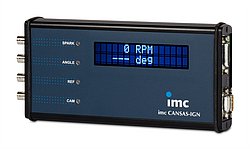
Das kompakte imc CANSAS-IGN ist speziell für die Messung des Zündwinkels und der Drehzahl an Verbrennungsmotoren mit bis zu 12 Zylindern konzipiert. Es reiht sich nahtlos in die Familie der CAN-integrierbaren Messmodule von imc ein.
- Hohe Abtastrate und Auflösung - selbst für hohe Motordrehzahlen
- CAN-Bus Ausgabe der berechneten Größen
- Zylindererkennung
- Snapshot-Modus (Einstellmodus): Das Rohsignal wird mit hoher Datenrate aufgezeichnet und anschließend über CAN-Bus ausgegeben
integrierbar, anpassbar, schnell

Im Zeitalter von Klimaschutz und steigenden Energiepreisen nehmen effektive und umweltschonende Motoren eine zentrale Rolle in den Entwicklungsprogrammen aller führenden Fahrzeughersteller ein. So wundert es nicht, dass sich viele Fahrzeugfirmen, Zulieferer und Serviceunternehmen zunehmend intensiver mit der Optimierung von Verbrennungsmotoren auseinandersetzen. Entscheidend für die Effizienzoptimierung ist es die Charakteristik der Motoren bestmöglich zu verstehen. Eine wichtige Information steckt dabei im Zündzeitpunkt bzw. Zündwinkel.
Bis dato waren Zündwinkelmessungen jedoch meist teuren und aufwendigen Spezialgeräten vorbehalten. Zudem lassen sich große autarke Analysatoren nicht einfach in einen vorhandenen Messaufbau integrieren.
Mit dem neuen imc CANSAS-IGN gehört dies nun der Vergangenheit an – das kompakte Messgerät ist ökonomisch und bietet für Prüfstands- und mobile Anwendungen wichtige Vorteile
Wie funktioniert imc CANSAS-IGN?
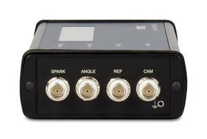
imc CANSAS-IGN misst mit hoher Abtastrate das Zündsignal, Kurbelwellensignal, Referenzsignal (Null-Impuls) und Nockenwellensignal und berechnet daraus den Zündwinkel sowie die aktuelle Motordrehzahl und gibt diese über den CAN-Bus aus.
 Zündsignal:
Unterstützt werden verschiedenste Methoden zur Signalerfassung, wie Zündzange, Abgriff der Primär- und Sekundärseite sowie Logiksignale.
Kurbelwellensignal:
Diverse Geber wie motoreigene induktive Näherungssensoren, Hallsensoren, Inkrementalgeber und Logiksignale werden unterstützt.
Referenzsignal:
Erlaubt den Anschluss des Nullimpulses bei Kurbelwellengebern mit separatem Nullimpuls.
Nockenwellensignal
Dient der optionalen Erfassung der Nockenwellenposition für eine Zylindererkennung. Beliebige Zahnkranzmuster des Nockenwellenrades werden unterstützt.
Alle Eingänge sind isoliert und voll konditioniert und verfügen über einstellbare Signalschwellen und Hysteresen.
Die gemessenen und berechneten Informationen wie Drehzahl und Zündwinkel der Zylinder werden über konfigurierbare CAN-Bus Ausgänge bereitgestellt. Somit lässt sich das Ergebnis direkt an eine Automatisierung übertragen oder über einen CAN-Datenlogger wie imc BUSDAQ oder ein modulares Messdatenerfassungssystem, wie imc CRONOSflex, aufzeichnen und mit anderen Daten kombinieren und vergleichen.
Die Konfiguration erfolgt einfach und schnell über die mitgelieferte Software imc CANSAS und jedes kompatible CAN-Bus-Interface für den PC. Grafische Oberflächen unterstützen bei der vollständigen Konfiguration der Signale wie Signalstärke, fehlende Zähne des Kurbelwellensensors, Schwellen und Hysteresen, Filterung und Ausgaberate auf CAN.
Zylindererkennung
Mit Hilfe des Nockenwellensignals kann aus dem allgemeinen Zündsignal erkannt werden, welcher Zylinder gerade zündet. Für bis zu 4 Zylinder (bei Motoren mit mehr als 4 Zylindern kann ausgewählt werden welche Zylinder) können dann fortlaufend Min-, Max- und Mittelwerte des Zündwinkels ausgegeben werden.
Konfiguration bleibt im Modul
Das imc CANSAS-IGN speichert seine Konfiguration auf einem internen Speicher und kann dadurch autark und ohne PC eingesetzt werden. So lässt sich das Modul bequem im Büro vorkonfigurieren und anschließend am Prüfstand oder im Fahrzeug verbauen.
Wenn ein genauer Blick gefragt ist
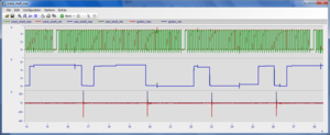
 Um das imc CANSAS-IGN passend parametrieren zu können, ist ein sogenannter Snapshot-Modus konfigurierbar. Das Modul nimmt dann mit hoher Datenrate einen kurzen Schnappschuss der Eingangssignale in einen Speicher auf. Anschließend wird der Inhalt des Speichers über den CAN-Bus mit langsamer Rate wieder ausgegeben. So kann der Anwender einen sehr guten Eindruck vom Verlauf des Signals erhalten. Damit wird es möglich sein, sinnvolle Pegel zur Flankenerkennung festzulegen. Aber es ist auch möglich, Vorverarbeitungen wie glättende Filter, AC-Schaltung etc. in ihrer Wirkung zu überprüfen.
Der Snapshot Mode ermöglicht....
- die genaue Analyse der Signale
- eine Überprüfung der Signalpegel um passende Triggerschwellen zu definieren
- eine Begutachtung der Signalpegel zur Einstellung der Hochpass- und Tiefpassfilter
Durch den Snapshot-Modus entfällt der Bedarf an zusätzlichem Equipment (wie z.B. einem Oszilloskop), wenn es um die Auswahl geeigneter Signalpegel für Signalflankendetektion geht. Darüber hinaus kann der Benutzer mit dem Snapshot Modus die Auswirkungen von Vorverarbeitungstechniken wie Glättungsfilter, AC-Kopplung usw. untersuchen.
About imc Test & Measurement
Productive testing is essential for the success of our customers—hence, our driving force. Since 1988 we have been committed to support industrial innovations with optimal measurement solutions. We are manufacturing our productive test and measurement systems at our headquarters in Berlin, Germany, operating worldwide in Europe, the US and Asia.
imc Test & Measurement is part of Axiometrix Solutions, a leading test solutions provider comprised of globally recognized measurement brands.
Kontakt
imc Test & Measurement AG Schweiz
Zürcherstrasse 310, CH-8500 Frauenfeld
Telefon: +41 52 722 14 55
E-Mail: info@imc-tm.ch
Hauptverwaltung | info@imc-tm.de
USA | accounts@imcdataworks.com
China | cnsales@imc-tm.com
UK | uk-sales@axiometrixsolutions.com
Spain | info@imc-tm.es
South Korea | hotline@imc-tm.kr
Switzerland | info@imc-tm.ch
© imc Test & Measurement GmbH. All rights reserved. Datenschutz. Meldung nach Hinweisgeberschutzgesetz. Impressum.


