Eisenbahn-Test- und Validierungszentrum
In Zusammenarbeit mit der Brademann + Broistedt GmbH & Co. KG wurde in einem Validierungsprüfzentrum in Deutschland ein Torsionsprüfstand für Züge modernisiert. Dieser Prüfstand ermittelt die Radaufstandskräfte bei Verwindung der Drehgestelle, um eine gleichmäßige Gewichtsverteilung zu überprüfen.
Anforderungen
Das Projekt stellt zwei wesentliche Anforderungen an den modernisierten Prüfstand: Zum einen muss er Züge und Zugelemente zur Gewichtsbestimmung verwiegen können. Zum anderen müssen die Radaufstandskräfte sowie die Radsatzaufstandskräfte (Summenkräfte) während der Verwindung des Zuges gemessen werden. Bei realen Einsätzen wird der Zug in jeder Kurve verwunden, da das äußere Gleis eine Überhöhung gegenüber dem inneren Gleis aufweist. Die Messung der Radaufstandskraft bei diesen Verwindungen ist besonders wichtig, da eine zu geringe Radaufstandskraft zum Entgleisen des Zuges führen kann. Das imc System verbindet beide Anforderungen in einer Lösung und bietet so einen effizienten und produktiven Weg die Erfordernisse zu erfüllen.
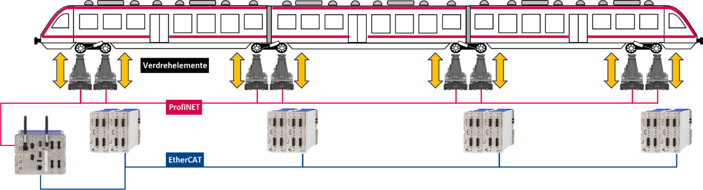
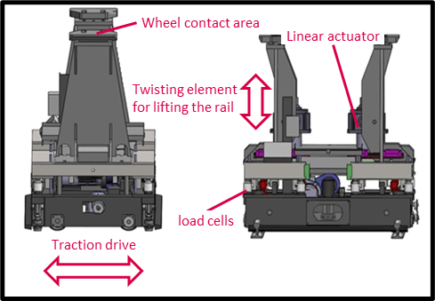
- Der Prüfstand besteht aus 8 Verwinde-Elementen, die zwischen 2 Schienen angebracht sind. Diese Elemente sind aus jeweils 2 höhenverstellbaren Radaufstandsflächen aufgebaut.
- Jede Seite kann bis zu 175 kN=17 t heben, ist unabhängig voneinander und wird über ProfiNET gesteuert
Jedes Verwinde-Element hat mehrere Antriebe:
- 2x Hubantrieb (je 1x Antrieb pro Aufstandsfläche), um die Verwindung einzustellen
- 2x Seitenverstellung, um den Zug herein und herauszufahren
- 1x Fahrantrieb, um die Elemente zu positionieren
- 1x Entlastungsantrieb, um das Verwiege-Element von der Schiene anzuheben
Der Prüfstand
gilt als das modernste Prüfzentrum zur Inbetriebnahme, Typprüfung und Abnahme von Schienenfahrzeugen weltweit. Dabei muss der Zug insbesondere nach der DIN 27201-5 über das „Prüfen von Rad- und Radsatzaufstandskräften der Eisenbahnfahrzeuge“ und nach der ORE B55 RP8 „Sicherheit gegen Entgleisen in Gleisverwindungen“ geprüft werden. Zur Prüfung wird der Zug in die Halle des Verwindeprüfstandes mit 8 Verwinde-Elementen gefahren und abgestellt. Danach wird ein im Excel-Format geladenes Prüfprogramm gestartet, bei dem der Zug in unterschiedlichen Stellungen statisch und dynamisch verwunden wird. Dies geschieht mit Hilfe von 16 (2 pro Verwinde-Element und 1 pro Rad) individuell höhenverstellbaren Hubelementen, die die Räder des Zuges unterschiedlich stark gegeneinander anheben (max. Höhenunterschied der Räder 150 mm). Die Aufstandskraft jedes einzelnen Rades wird mit Hilfe von 4 Kraftmessdosen pro Hubelement während des gesamten Verwindevorgangs gemessen. Durch den Einsatz eines Nivelliergeräts kann die Position der Räder auf 1/10 mm genau bestimmt werden. Diese „Startposition“ wird vor der Prüfung manuell gesetzt, um den gemeinsamen Referenzpunkt für alle Elemente in einer Ebene zu sehen.